Add products by adding codes
Communication protocols in industry


Communication Protocols in Industry
In industrial automation, open communication protocols are key in enabling data exchange between PLC controllers, sensors, meters, and supervisory systems. Modbus (in RTU, ASCII, and TCP/IP variants), M-Bus (Meter-Bus), and physical interface standards such as RS-232 and RS-485 are among the most popular protocols.
RS-232 – The Basic Serial Interface
RS-232 is a traditional point-to-point serial transmission standard (a single transmitter and receiver), widely used for communication between computers/PLCs and peripheral devices. The transmitted signals are single-ended voltage signals, typically ranging from ±3 V to ±15 V. Transmission speeds usually reach up to a few hundred kbps (e.g., 115.2 kbps), with a range limited to several meters (typically around 15 m). RS-232 operates in full-duplex mode (separate Tx and Rx lines) and requires a common ground. Key features and applications include:
- Physical parameters: A logic “0” corresponds to a voltage of +3 V to +15 V, while a logic “1” is –3 V to –15 V relative to ground. A simple level-shifting circuit (e.g., MAX232) is required to convert to standard TTL levels.
- Transmission mode: Asynchronous serial, typically using 8N1 format (8 data bits, no parity, 1 stop bit). It lacks native multi-device support — only two endpoints can communicate simultaneously.
- Typical applications: Connecting operator panels, modems, simple sensors, or transducers to PLCs or computers. Commonly used for debugging and sending text-based commands.
- Limitations: Short transmission range (a few hundred meters at low speeds) and no multi-drop capability (point-to-point only).

RS-485 – Differential Bus
RS-485 (ANSI/TIA/EIA-485) is a standard that enables differential (balanced) serial transmission over two wires (commonly labeled A and B). Its main advantages include long transmission distances and support for bus topology with multiple nodes. Key features of RS-485 include:
- Topology and range: RS-485 supports a multipoint line, allowing at least 32 receivers (loads) to be connected to the same bus. At lower baud rates, it can achieve distances of up to ~1200 m.
- Differential transmission: Signals are transmitted as the voltage difference between wires A and B, which provides high noise immunity and eliminates ground potential issues. The receiver's threshold voltage difference is around ±200 mV.
- Transmission speed: Typically up to 10 Mbps over short distances. The “bit/s × meter ≤ 10⁸” rule helps estimate the maximum range at various data rates.
- Operating mode: Most commonly used in half-duplex mode (the same wire pair is used for both transmitting and receiving, requiring master/slave arbitration). The transmitter controls the line direction.
- Typical applications: Sensor and device networks in industrial automation, HVAC systems, smart buildings, and industrial metering. RS-485 often serves as the physical layer for protocols such as Modbus RTU or M-Bus in expanded metering systems.
Comparison with RS-232: Unlike RS-232, RS-485 supports longer distances and a multipoint bus topology. It allows multiple devices to share a single bus, which is not possible with a simple RS-232 point-to-point setup.
For RS-485 networks, a variety of isolated repeaters and hubs (splitters) are available. For example, the R02 is our best-selling RS-485 repeater with 3 kV isolation, used to boost signal strength and connect additional segments. The H01 (and models H02, H03) are isolated 1-to-3 RS-485 hubs that split the bus into three branches while maintaining galvanic isolation. These are ideal for connecting multiple sensor subnets to a single controller port.
Modbus RTU and Modbus ASCII – Serial Protocols
Modbus RTU/ASCII are application-layer protocols typically operating over RS-485 or RS-232 links. They use a master–slave (also known as client–server) communication model: one device (the master) initiates communication by sending requests, and the others (slaves) respond. In Modbus terminology, a "master" corresponds to a client, while a "slave" refers to a server. In SCADA systems, for instance, a central computer or PLC acts as the master, collecting data from meters or sensors, which act as slaves.
Modbus RTU
- Uses a binary frame with a 16-bit CRC checksum.
- Data (device address, function code, payload) is transmitted in a continuous binary stream, making RTU more efficient than ASCII due to lower transmission overhead.
- It requires strict control of timing gaps between characters.
Modbus ASCII
- All fields (address, function, data) are encoded as ASCII characters (7-bit, usually letters and hex digits).
- The frame starts with a colon and ends with a CR/LF sequence.
- Errors are checked using an LRC (Longitudinal Redundancy Check).
- It's easier to inspect manually, but it has a higher transmission overhead (requiring about twice as many bits as RTU) and lower effective speed.
Typical applications for Modbus RTU/ASCII: Communication in automation and measurement systems (controllers, transducers, meters) where simple and reliable data exchange is required. Modbus RTU is a de facto standard in many industrial applications (e.g., temperature sensor networks, HVAC control systems). ASCII is less common and mainly used where human readability or text framing is needed.
RTU vs ASCII comparison: RTU is faster and more compact (binary format, CRC), while ASCII is easier to debug (text format, LRC, ":" and CR/LF framing). ASCII requires about twice the number of bits, making it slower.
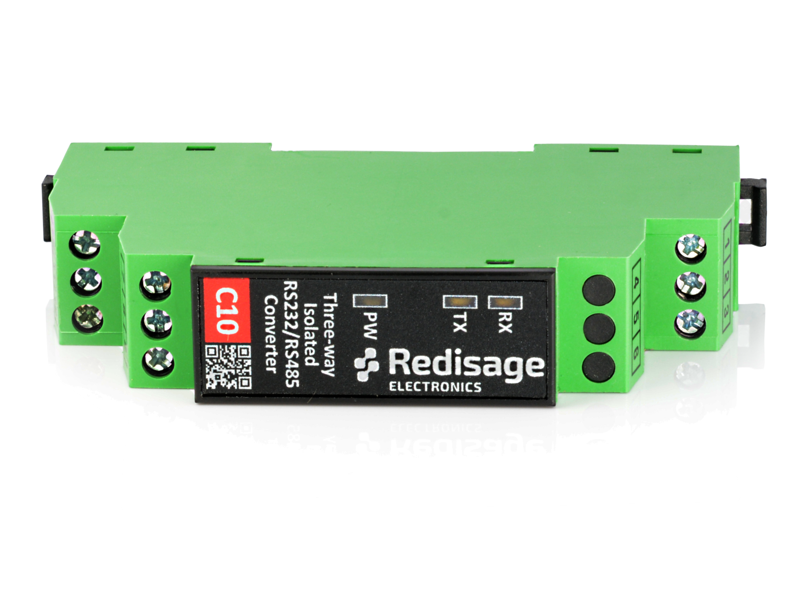
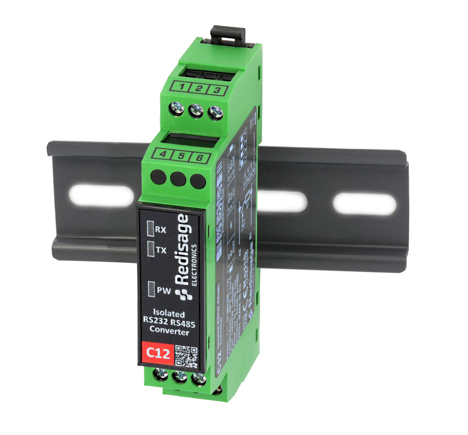
Hardware support for Modbus RTU/ASCII typically involves Modbus gateways and serial converters. Redisage offers gateways like G01 and G02, which support Modbus TCP, RTU, and ASCII simultaneously. The G01 model includes Ethernet (for Modbus TCP) and two RS-232 ports, enabling conversion from Ethernet-based Modbus TCP to RS-232-based RTU/ASCII. The G02 model works similarly but uses an RS-485 port. Additionally, traditional RS232↔RS485 converters from the C10–C12 series (with 3 kV isolation) can be used to build Modbus RTU lines, helping integrate non-Ethernet devices into a Modbus network.

Modbus TCP/IP – Modbus Over Ethernet
Modbus TCP (also known as Modbus TCP/IP) is a variant of the Modbus protocol adapted for Ethernet networks. Unlike its serial counterparts, Modbus messages are encapsulated in TCP packets (using port 502). Key characteristics:
- Operation: A client (master) connects to a server (slave) using an IP address and port 502. The Modbus frame consists of an MBAP header (address, data length, etc.) and a PDU (function code + data).
- No CRC: Since Ethernet/TCP/IP layers already include checksums, Modbus TCP does not require a separate CRC/LRC, simplifying hardware implementation and reducing overhead.
- Advantages: Faster transmission (Ethernet supports hundreds of Mbps), seamless integration with IT infrastructure (switches, routers), and support for multiple simultaneous connections (multiple masters/slaves). Modbus TCP enables extensive, scalable networks — for example, distributed meter readings or wireless gateways — while maintaining compatibility with the Modbus protocol.
Typical applications: SCADA and IoT systems requiring fast, network-based communication. Modbus TCP is widely used in large facilities that bridge industrial hardware with Ethernet/Internet layers (e.g., remote measurement monitoring, legacy device integration through Ethernet gateways).
As with Modbus RTU, Redisage’s G01 and G02 gateways are the primary tools for Modbus TCP. They offer transparent transfer of Modbus commands over Ethernet. The product range also includes wireless gateways and Modbus TCP routers, but the G01/G02 modules remain the core solution, bridging Ethernet with standard serial interfaces (RS-232/485) in any Modbus variant.
M-Bus – Bus System for Remote Meter Reading
M-Bus (Meter-Bus) is a European standard (EN 13757) specifically designed for remote reading of utility meters (water, gas, electricity, heat). It operates in a master–slave communication model, where a central unit (master) periodically polls connected meters (slaves) for their current readings. Key features of M-Bus:
- Two-wire bus: The wired version uses a 2-wire signal line (similar to RS-485, but optimized for a single pair and additional functionalities). The bus can also supply power to passive devices (such as meters) in simple implementations. Thanks to its two-wire design, it is relatively inexpensive and easy to install.
- Master–slave: A single master can handle up to ~60 meters on the bus (in passive mode). Meters respond sequentially, each with its own unique address. M-Bus is resilient to power interruptions (devices can be battery-powered) and is optimized for low power consumption.
- Speed: The transmission rate is low (typically up to 9.6 kbps), but the goal is reliable measurement reading rather than high data throughput.
- Typical applications: Metering installations in residential and industrial buildings – a central module (or mobile terminal) collects readings from heat, water, or gas meters, often as part of energy management systems. It is used where remote data aggregation is essential, and minimal wiring is preferred.
Comparison with Modbus: M-Bus is purpose-built for meter reading and includes its own application layer (EN 13757-3), while Modbus is a general-purpose industrial protocol. Both can operate over physical RS-232/485 layers or via converters, but M-Bus uniquely allows simultaneous power and data transmission over a simple two-wire line.
Wireless M-Bus – The Wireless Version of the M-Bus Protocol
Wireless M-Bus (wM-Bus) is an extension of the M-Bus standard (compliant with EN 13757-4), enabling wireless data transmission from utility meters (water, gas, electricity, heat) to higher-level systems. Unlike its wired counterpart, wM-Bus utilizes ISM bands (most commonly 868 MHz in Europe) and allows for point-to-multipoint communication (a master with multiple meters). The protocol defines various operating modes (e.g., S, T, C, R), tailored to specific application requirements—for instance, unidirectional, bidirectional, or low-power operation. Key features of Wireless M-Bus include:
Transmission Modes: Examples include T1 (meter transmits periodically only), C1 (bidirectional communication), and S1 (periodic unidirectional transmission). These are adapted for various reading scenarios, such as remote reading or temporary meter contact (e.g., by a meter reader).
Range and Reliability: It offers a range of up to several hundred meters in open areas. Transmission is resistant to interference due to the use of FSK modulation and data retransmission.
Energy Efficiency: Battery-powered meters can operate for many years thanks to energy-saving modes and infrequent transmissions.
Applications: Modern Smart Metering systems, distributed meter reading in multi-family buildings, district heating and water supply networks, and integration with IoT systems.
Wireless M-Bus is becoming a standard in modern metering systems due to its ease of installation, elimination of cabling, and the ability to integrate with wireless gateways (e.g., LTE/LoRaWAN/Wi-Fi). This allows for the creation of scalable and flexible remote reading systems.

The Growing Importance of Wireless Protocols in Industrial Automation
With the dynamic development of Internet of Things (IoT) technologies and Industry 4.0, wireless communication protocols such as Wi-Fi, Bluetooth, ZigBee, LoRa, NB-IoT, and LTE-M are playing an increasingly important role in industrial automation. Their advantages are particularly evident in scenarios where deploying traditional wired infrastructure would be costly, difficult, or even impossible — for example, in facilities covering large areas, rotating machine parts, or mobile installations. Wireless data transmission enables easy and fast integration of various end devices, sensors, controllers, and cloud systems without the need to interfere with existing infrastructure.
Wi-Fi provides fast access to local networks and the internet, allowing for remote monitoring and device management via desktop, mobile, or web applications. Bluetooth Low Energy (BLE) is primarily used where energy efficiency and short-range communication are key, such as in sensors, diagnostic devices, or operator interfaces. On the other hand, long-range protocols like LoRa are ideal for applications where data transmission is infrequent but must cover long distances — for instance, in precision agriculture, environmental monitoring, or management of distributed industrial infrastructure.
Devices available at redisage.com are increasingly equipped with interfaces that enable wireless connectivity, either through dedicated modules or integrated microcontrollers with built-in Wi-Fi or Bluetooth support. Examples include modern communication gateways, protocol converters, or controllers with embedded ESP32 modules or other SoCs supporting wireless networking. This enables the creation of flexible, scalable, and cost-effective automation systems that meet the growing demands of modern industry and align with the concept of digitalization and remote process management.
Interface Conversions
In practice, it is often necessary to connect devices with different types of communication interfaces. Redisage offers a comprehensive range of converters and repeaters for various interface types:
RS232↔RS485 Converters
- Devices C10 and C12 provide 3 kV isolation and automatic direction control.
- They enable seamless bidirectional communication between equipment with an RS-232 port and an RS-485 bus.
M-Bus ↔ RS-232/RS-485 Converters
- The C01–C04 series allows connection of an M-Bus meter to an RS-232 port (in passive or active mode) or an RS-485 bus.
- This makes it possible for a reading device or controller with a serial port to communicate with an M-Bus network.
Repeaters and Signal Boosters
- Devices R01–R04 are linear repeaters – R01/R02 amplify RS-485 signals (R01: 3-port, R02: 1-port), while R03/R04 serve the same purpose for RS-232 (R03: 3-port, R04: 1-port).
- Their use allows signal extension and isolation of individual bus segments.
- It's also worth to mention the C05-C08 devices. While their primary function is protocol conversion, they can also be used as M-Bus signal repeaters in Master/Slave mode.
RS-485 Hubs
- Models H01–H03 are isolated 1:3 RS-485 bus splitters.
- They allow you to build a signal “splitter” with one master input and three outputs to separate sensor subnets.
Transmission Modes
- Many converters support both passive mode (for M-Bus signals where the device is externally powered) and active mode (where the meter receives power from the converter).
- For example, C01 converts passive M-Bus signals to RS-232 output, while C02 supports active mode.
These devices enable the creation of a flexible communication infrastructure and facilitate the integration of different protocols and physical layers.
Recommended

C10 - RS232 to RS485 Converter (3-Way 3kV Isolation)

C12 - RS232 to RS485 Converter (Isolation on RS485 Side)


C04 - M-Bus 10 Master to RS232/RS485 Converter

C05 - M-Bus 60 Master to RS232/RS485 Converter
 Special offer